AddThis

Bookmark and Share

Monday 23 June 2014

New Engineering project topics


SOLAR ENERGY INSTALLATION- FOR BSC
AUDIO AND POWER AMPLIFIER- FOR BSC
BATTERY CHARGERS (CELL PHONE, CAR) – FOR BSC
ALARMS OF DIFFERENT TYPES- FOR BSC
TOUCH ACTIVATED SWITCH AND ALARMS- FOR BSC
AM-FM-SW-TV ACTIVE ANTENNA- FOR BSC
FM TRANSMITTER – FOR BSC
WATER LEVEL INDICATOR WITH ALARM- FOR BSC
AUTO TURN-OFF BATTERY CHARGER- FOR BSC
RAIN ALARM- FOR BSC
REMOTE CONTROL AC LAMP- FOR BSC
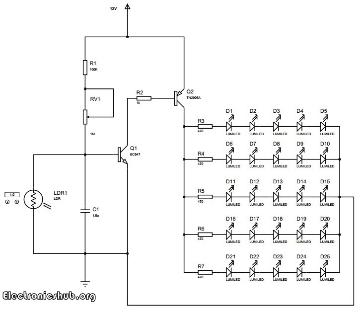
DARK AUTOMATED SWITCH- FOR BSC
MOTORCYCLE ALARM – FOR BSC
DC-AC INVERTER WIT 555 TIMER- FOR BSC
BREAK LIGHT FLASHER- FOR BSC
VOLTAGE COMPARATOR- FOR BSC
FUSE MONITORING ALARM- FOR BSC
AUDIO MIXER – FOR BSC
SOLAR CELL PHONE CHARGER- FOR BSC
AUTOMATIC TRICLE CHARGER- FOR BSC
TONE CONTROL- FOR BSC
AUTO DAYLIGHT ALARM- FOR BSC
HIGH AND LOW VOLTAGE CUT-OUT WITH DELAY- FOR BSC
TRANSMITTER ORGAN- FOR BSC
AUTOMATIC OVEN CONTROLLER- FOR BSC
UPS POWER SUPPLY- FOR BSC
SEVEN SEGMENT LED COUNTER – FOR BSC
AUTOMATIC VOLTAGE REGULATOR- FOR BSC
GATE ALARM- FOR BSC
HEADPHONE ALARM – FOR BSC
FULL-DUPLEX INTERCOM- FOR BSC
CHRISMAS LIGHT- FOR BSC
FIRE DOOR ALARM- FOR BSC
AUTO FAN SPEED CONTROLLER – FOR BSC
MINIATURE FM TRANSMITTER- FOR BSC
AC LINE CURRENT DETECTOR- FOR BSC
VARIABLE POWER SUPPLY- FOR BSC
ZENER DIODE TESTER- FOR BSC
FM RECEIVER- FOR BSC
ULTRASONIC PEST REPELLER- FOR BSC
POWER SUPPLIERS – FOR BSC
WATER ACTIVATED ALART- FOR BSC
WATER LEVEL INDICATOR WITH ALARM- FOR BSC
POWER FAILURE ALARM- FOR BSC
SELF ACTIVATING POWER SUPPLY- FOR BSC
MICROPHONE MIXER – FOR BSC
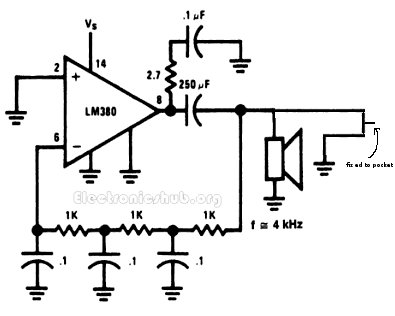
EMERGENCY SIREN SIMULATOR- FOR BSC
TRANSFORMERLESS POWER SUPPLY – FOR BSC
DESIGN AND CONSTRUCTION OF A 2000W INVERTER
DESIGN AND CONSTRUCTION OF A D.C TO A.C INVETER SYSTEM
THE CONSTRUCTION OF A 3-PHASE MOTOR OPERATION INDICATOR
CONSTRUCTION OF PVS CONDUIT WIRING SYSTEM OF TWO BEDROOM BUNGALOW
CONSTRUCTION OF A 12 VOLT BATTERY CHARGER
CONSTRUCTION OF AUTOMATIC CHANGE OVER WITH GENERATOR TRIP OFF

Sunday 22 June 2014

Auto Night Lamp Using High Power LED

Auto Night Lamp Using High Power LEDs is a circuit which turns ON the LED lights interfaced to it at night time and it turns OFF the lights automatically when it is day. Usage of LEDs is growing day by day due to the advantages they provide compared to the conventional filament bulbs or fluorescent lamps. They provide good quality of white light with a better intensity compared to others. They also consume less power compared to their alternatives. These are the advantages which the LEDs encourage us to use them compared to their alternatives.
In this article, we shall see the circuit and the working of turning on or off of high power LEDs with light intensity. The element which is used for sensing light in the circuit is the light dependent resistor. The resistance of the light dependent resistor depends on the light incident on it. If the intensity of light incident on it is more, then the resistance of the circuit decreases. If the intensity of light incident on it decreases, then the resistance of the device increases. We are making use of this property of the light dependent resistor to detect the light and thereby operate the LEDs. We are arranging twenty five light emitting diodes in an array such that five LEDs are in series and five such series LEDs are arranged in parallel.
The transistors are used in saturation mode. They are used as electronic switches in this mode. The transistor BC547 is a general purpose NPN transistor which is used to further switch the LEDs. This is a power transistor with a heat sink. The heat sink helps the transistor to dissipate the generated heat into air so that the transistor can handle higher power loads than it can do without the heat sink.
The entire circuit along with the LEDs is powered by a 12V DC power supply. A battery based DC power supply is usually preferred. However, you can use a ac rectified and regulated power supply.
The LEDs used in the circuit are high powered white LEDs. The intensity of light produced by these LEDs equals an ordinary fluorescent bulb. The lighting produced is sufficient for reading or to do any other daily activity. The circuit can be assembled on a printed circuit board with all the components neatly arranged and the LEDs placed in order. Try to place the LEDs maintaining a distance of about 1 cm between the LEDs so that the the lighting will be well distributed in your room.

Pull Pin Security Alarm System

his circuit helps us to get alerted when anybody picks our pockets or bags. The circuit is very helpful to prevent our goods getting pick pocketed. The circuit is called a pull pin security alarm because it gets activated as soon as the pin is pulled.
The arrangement of the circuit is as follows. The circuit has a pin which is fixed to the pocket and the other end is attached to the circuit. The circuit remains inactive until the wallet is in your pocket as the circuit gets activated when the wallet is pulled from your pocket.
When the wallet is in the pocket, the circuit has the pin attached thereby the circuit remains inactive. Whereas when the wallet is removed from the pocket, the pin gets detached from the circuit thereby the circuit gets activated. When the circuit gets activated, the circuit turns ON the mini loudspeaker. The mini loudspeaker is fed with an alternating signal of audio frequency. This signal vibrates the loud speaker at an audio frequency so that it is well heard to us.